Energy numbers for optical links are easy to improve by changing the accounting boundary. A modulator can be described as efficient if only its electrical drive is counted. Its optical loss then appears in a separate laser budget. A transmitter can omit the equalizer because the host SerDes already contains one, while the host reports that processing as general I/O overhead. Every component looks better, but the rack still pays the sum.
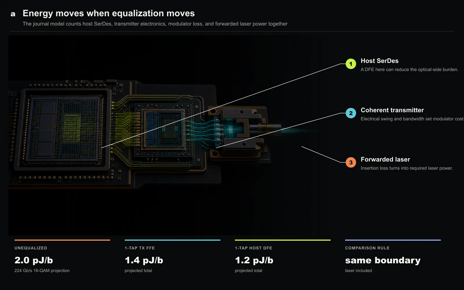
The 2025 Journal of Lightwave Technology paper from Antroy Roy Chowdhury, Wahid Rahman and Vladimir Stojanovic is useful because it fixes this boundary. The authors build a closed-form model for a linear-drive, laser-forwarded coherent silicon-photonic transmitter and include electrical swing, device parameters, bandwidth, equalization and laser power in one optimization[1][2]. For a 224 Gb/s 16-QAM link, the model projects 2.0 pJ/b without equalization, 1.4 pJ/b with a one-tap transmitter feed-forward equalizer (FFE), and 1.2 pJ/b when a one-tap decision-feedback equalizer (DFE) is placed in the host SerDes[1].
These values are modeled projections, not measured package results. Their importance lies in the direction of the optimum. A small amount of signal processing can allow a lower-swing or more bandwidth-limited optical transmitter, reducing the combined electronics and laser energy. The lowest value appears when the host absorbs the equalization work, which immediately raises an ownership question: does the optical engine save energy, or does the system save energy after work moves across the package boundary?
Laser-forwarded changes where heat and loss are paid
A laser-forwarded architecture keeps the light source away from the hot optical engine and routes continuous-wave light to the package. The modulator encodes data onto that light near the switch or accelerator. Separating the laser can improve serviceability and temperature stability, and several optical engines can share a laser bank. It also creates a distribution path whose splitter, connector, waveguide and coupling losses must be covered before useful light reaches the modulator.
That distinction makes wall-plug power essential. If the laser converts electrical power to optical power at a stated efficiency, every additional decibel of path or modulator loss increases its electrical demand. A transmitter that reduces driver swing by choosing a more lossy operating point can move energy from the driver to the laser. Optimizing one device cannot find the link minimum.
The model therefore treats delivered optical power rather than nominal laser output as the relevant quantity. This is the correct system boundary for CPO. External laser placement, fiber route and optical fan-out may differ across products, but the receiver needs a target optical signal-to-noise ratio. The electrical cost to deliver that signal must remain attached to the lane.
Thermal separation has a second-order effect. A remote laser can operate at a controlled temperature while the modulator sits beside a high-power die. The modulator’s bias and insertion loss still move with local temperature, which changes the required forwarded power. A practical controller must track this variation and reserve aging margin. The model identifies the design direction; a package must show the distribution across temperature and time.
Coherent signaling makes linearity a shared resource
16-QAM carries four bits per symbol through amplitude and phase. The transmitter must preserve the position of each constellation point sufficiently well for the receiver to recover it after noise and channel distortion. Electrical driver nonlinearity, modulator transfer shape, limited bandwidth, phase imbalance and laser noise all contribute to the error vector.
A conventional design may oversize the driver bandwidth and swing to keep the optical waveform clean. That choice is robust but expensive. Co-optimization asks whether a deliberately imperfect analog path can be corrected by a small digital filter. If one equalizer tap permits a lower-energy driver or a more efficient modulator bias, the total can fall even after the filter energy is counted.
The transmitter FFE shapes the outgoing symbols based on current and previous data. It can compensate predictable bandwidth loss before the signal enters the optical path, but it increases digital switching and may enlarge the required output range. A host DFE operates on detected decisions and subtracts estimated intersymbol interference without increasing transmitted swing. It can therefore be more energy-efficient in the model, although error propagation and receiver timing must be controlled.
This does not establish that a one-tap DFE is always best. The channel response, data converter architecture, process node and error target determine the cost of each tap. The published result shows that equalizer placement is a first-order architectural variable for the studied transmitter, not a universal number that can be copied to another link.
The 2.0, 1.4 and 1.2 pJ/b points form a decision curve
The unequalized 2.0 pJ/b point is the baseline under the paper’s device and link assumptions. It asks the analog transmitter and optical path to satisfy the 224 Gb/s 16-QAM target without digital compensation. Adding a one-tap transmitter FFE changes the optimum and lowers projected total energy to 1.4 pJ/b. Moving the one-tap correction to a host DFE lowers it further to 1.2 pJ/b[1][2].
The 40% difference from 2.0 to 1.2 pJ/b should not be interpreted as free host processing. The DFE is inside the accounting model. The result means its added energy is smaller than the driver and laser energy avoided under the assumed constraints. If a deployed SerDes already contains an idle or reusable DFE structure, the marginal cost may be lower still. If the host requires a new high-speed data path or clock domain, implementation cost could be higher.
The curve also indicates where specifications should be negotiated. An optical-engine supplier may guarantee an electrical eye at its package pins, while a switch designer may specify the equalized bit-error rate after the host receiver. Without a shared channel model, both sides add margin and the system overdesigns the same impairment twice. Co-design replaces duplicated margin with an explicit allocation.
Comparisons must keep the same reach, symbol rate, coding and error target. A lower pJ/b number obtained at shorter reach or with more FEC cannot be placed on the same curve. Likewise, energy should be reported for the same number of usable bits after coding. The paper’s method is more transferable than any single result because it requires these assumptions to enter the model.
Closed-form models are valuable precisely because they are incomplete
A closed-form model simplifies circuit and device behavior into equations that can be evaluated quickly. It can sweep electrical swing, capacitance, modulator efficiency, optical loss, bandwidth and equalizer settings without fabricating every combination. This is appropriate early in CPO design, when package and process choices need to be narrowed before expensive test silicon.
The simplification also sets the evidence limit. Parasitics may be frequency-dependent, modulator response can be nonlinear, and package loss can vary across lanes. Clocking, calibration, monitor photodiodes, safety controls and redundancy may not fit a compact expression. A model optimum can move when these fixed overheads are added.
Sensitivity is therefore more useful than one minimum. Architects should vary laser efficiency, coupling loss, temperature, device capacitance and equalizer energy over realistic distributions. If the same architecture remains near-optimal, the conclusion is robust. If a small loss change flips the choice between transmitter FFE and host DFE, the product needs adaptive control or a larger margin.
The later ISSCC 2026 measurement by the related team is a helpful but separate piece of evidence. It demonstrates a 212 Gb/s coherent transmitter operating point with a compact direct-driven MZM[3]. It does not validate every parameter in the 2025 model, but it shows that the general electronic-photonic design direction can produce high-rate silicon. Model and measurement should be connected through matched assumptions, not treated as interchangeable proof.
Equalization placement is an ownership and telemetry problem
Putting the DFE in the host can lower modeled link energy, but the optical engine then depends on host signal processing. The interface contract must expose the channel state needed to configure that filter. A fixed preset may work for a narrow process and temperature range; a deployed system will likely need training, monitoring and fault detection.
Telemetry must identify whether margin is being lost in the electrical route, modulator, laser distribution or receiver. Otherwise the host may increase equalization when the real problem is optical power, hiding degradation until the correction range is exhausted. CPO management should report laser current, received optical power, bias, temperature and error statistics together with equalizer settings.
Failure containment also changes. If several optical lanes share a host equalizer block or laser source, one control failure can affect multiple links. Redundant lasers and lane remapping help only if the control plane can localize the cause. The energy optimum cannot be separated from the operational architecture that maintains it.
Software ownership matters during upgrades. A host firmware change can alter DFE behavior and therefore the validated optical margin. Optical-engine qualification must specify compatible presets and training sequences. Conversely, replacing an optical tile with a different loss profile may require host changes. The design saves energy by crossing a component boundary, so configuration control must cross it as well.
What measurement should follow the model
The clearest validation would implement the three configurations on the same transmitter and receiver: unequalized, one-tap TX FFE and one-tap host DFE. Power should be measured at the electrical rails and laser wall plug, with identical delivered bits, fiber reach, temperature and post-FEC target. Optical loss should include connectors and distribution expected in the package.
The experiment should sweep process, voltage and temperature rather than report one optimum. It should show error vector magnitude, pre-FEC bit-error rate, correction margin and total energy by lane. Control, clocking and adaptation energy should be included. If equalization moves into a host block already needed for another function, both total and marginal energy should be reported.
Multi-lane behavior is essential. Shared laser noise, supply coupling and thermal gradients can correlate errors across lanes. A model based on one lane may miss the power and margin needed when many coherent transmitters operate together. Package-level validation should therefore state aggregate lane count and simultaneous activity.
Finally, aging must be translated into energy. If coupling loss or laser efficiency degrades, the controller may raise laser power while the link continues to pass. Availability remains high but energy drifts away from the published point. Long-term telemetry should reveal that change rather than treating successful error correction as proof that nothing changed.
The system insight: optimization needs one bill
The paper’s central contribution is an accounting rule. The host, optical transmitter and laser distribution are not independent energy islands. Changing electrical swing alters modulator behavior; optical loss alters laser power; bandwidth alters equalization; equalizer placement alters which chip pays. A component minimum can be a system maximum when those couplings are ignored.
For CPO procurement, every pJ/b claim should therefore answer four questions. Does it include laser wall-plug power? Where is optical loss measured? Which equalization and FEC functions are included? Is the number measured or modeled at the stated temperature and reach? Products that use different boundaries cannot be ranked by the headline alone.
The 1.2 pJ/b projected point is not yet a product promise. It is evidence that a single host DFE tap can be worth more than extra analog bandwidth under a defined 224 Gb/s coherent link model. That insight is actionable because it changes partitioning before silicon is fixed. The broader lesson is durable: CPO removes distance from the electrical path, but it will remove energy only when electronics, photons and host processing are charged to the same bill.
The model as an interface artifact
Co-optimization is most valuable when it survives organizational boundaries. The optical-engine team, SerDes team and package team should exchange a compact model with named reference planes rather than independent spreadsheet totals. Electrical swing should be defined at the driver output, optical loss at physical coupling planes, laser efficiency at the wall plug and error performance after a stated receiver and FEC chain. Versioning those assumptions makes a pJ/b change explainable.
The same artifact can guide adaptive operation. If temperature increases modulator loss, the controller can compare the energy cost of more laser power with a different bias or equalizer preset. If aging raises the required optical margin, the system can decide whether to remap a lane before the laser reaches its limit. A static optimum becomes a policy over measurable state.
This is a stronger use of the paper than copying 1.2 pJ/b into a roadmap. The numerical optimum will change with process, laser and reach. The shared boundary and optimization variables remain useful. They let design teams ask whether a new device removes energy, changes where it is paid or only changes which organization reports it.
Source and copyright notice
This article is an independent Silicon & Systems editorial analysis based on the Journal of Lightwave Technology paper and Optica’s official abstract and article history. The reported energy values are identified as model projections, and all system implications are our analysis. We do not reproduce the source paper’s prose, equations, plots or tables. The hardware plate was created specifically for this article. The source paper copyright is (c) IEEE 2025. See doi:10.1364/JLT.43.004338.