AI networks already divide one fiber into wavelengths. A conventional optical circuit switch then chooses which fiber port receives the aggregate signal. The ECOC 2025 paper from the University of Cambridge, NVIDIA, and Ghent University-imec asks whether the switch should control both dimensions independently[1]. Its silicon-photonic space-and-wavelength selective switch (SWSS) accepts four spatial inputs, exposes four outputs, and selects among eight wavelength channels. A controller can move one wavelength without moving every other channel sharing the same fiber.
This granularity is attractive for accelerator clusters. A rack can add bandwidth between two busy endpoints without dedicating a complete fiber bundle, and a memory pool can receive one channel while other channels retain their previous destinations. However, an extra routing dimension also adds resonators, interferometers, couplers, and waveguides to the optical path. The paper’s most important result is therefore not the count of possible routes. It is the first system test showing that commercial NVIDIA InfiniBand interfaces pass traffic through the fabricated switch, accompanied by a loss number that explains why the design is not yet a production fabric.
Space and wavelength solve different allocation problems
A space switch maps input fibers to output fibers. If four wavelengths enter together, they normally leave together. A wavelength-selective element can separate those channels, but one filter alone does not provide a scalable nonblocking spatial fabric. The proposed SWSS combines both. Microring resonators (MRRs) select narrow spectral bands efficiently, while Mach-Zehnder interferometers (MZIs) supply broader and more stable spatial routing. The result can direct wavelength λ1 from input 1 toward one output and λ2 toward another.
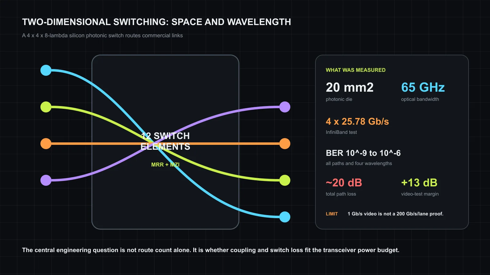
The architecture uses a modified dilated Banyan topology. Twelve 2x2x8-lambda switch elements and passive combiners implement the 4x4 fabric. Dilation provides alternative internal paths that cancel first-order in-band crosstalk, a serious issue when a strong channel leaks into another route at the same wavelength. The twelve elements occupy 0.6 mm² inside a 20 mm² photonic die. The layout leaves 200 micrometers between neighboring microrings to reduce thermal coupling.
That spacing highlights a system tradeoff. More wavelengths and ports increase route count faster than die edge length, but each thermally tuned resonator needs isolation and control. Compactness can amplify thermal crosstalk; generous spacing expands waveguides and loss. The current 4x4 device is large enough to test the concept and small enough that the authors can characterize every input-output-wavelength combination. Scaling to dozens of ports is not a direct multiplication of the demonstrated block.
The spectrum says the filters work
The first measurement routes four O-band channels from one input to one output using a commercial QSFP28 transceiver. Every channel shows more than 27 dB extinction ratio and approximately 65 GHz optical bandwidth. Extinction ratio indicates that a selected route can distinguish the passing state from the suppressed state. The bandwidth measures the optical passband, not an end-to-end 65 GHz electrical link.
The distinction matters because the paper later discusses 200 Gb/s per wavelength as a future possibility. A 65 GHz optical passband can accommodate faster modulation than the 25.78 Gb/s channels used in the system test, given suitable transmitters, receivers, equalization, signal-to-noise ratio, and link budget. The device does not demonstrate a 200 Gb/s lane. The claim is a bandwidth-based projection contingent on future transceivers.
Microrings also move with temperature and process variation. The fabricated die demonstrates that a controller can align its channels under laboratory conditions. A deployed switch would need calibration, heater or electro-optic control, drift monitoring, and a policy for channels that no longer meet the loss or isolation target. Those control costs are outside the reported bit-rate result.
Commercial InfiniBand makes the experiment concrete
For the main datacenter test, the team connects an NVIDIA Mellanox NIC to a host through PCIe and installs a pair of 100G QSFP28 modules. The modules carry four O-band wavelengths spaced by 4.5 nm and are specified for reach up to 40 km. The test path includes 500 m of single-mode fiber, the photonic switch, and a loopback to the second transceiver. NVIDIA firmware tools configure the module’s PRBS31 test mode and read raw errors from the NIC.
Each wavelength runs at 25.78 Gb/s. The authors test every combination of four inputs, four outputs, and four wavelengths. Reported BER spans 10^-9 to 10^-6. This is stronger evidence than measuring an isolated resonator because the path includes commercial optics, fiber, the fabricated switch, and the actual NIC diagnostics. It proves that the switch routes an aggregate 100G interface across all tested states.
The result is not error-free Ethernet or InfiniBand service under a specified FEC target. A raw BER of 10^-6 is several orders of magnitude worse than 10^-9 and would depend on forward-error correction and receiver margin for reliable operation. The paper attributes the spread primarily to insertion loss. Fiber coupling, the switch, and waveguides produce roughly 20 dB of total loss on each path. That number, more than the best BER, defines the engineering work still required.
The video demonstration tests margin, not AI bandwidth
The second setup uses commercial Ethernet switches and 10G SFP+ modules. PCs aggregate multiple 4K video streams to approximately 1 Gb/s, limited by the host NIC. The optical signal passes through the programmable switch, and an attenuator progressively reduces received power. Video remains stable with another 13 dB of attenuation, establishing at least that much dynamic range for this setup.
This is a useful robustness experiment, but it should not be interpreted as a high-speed AI workload. The host runs at roughly one percent of the aggregate rate exercised by the InfiniBand test and far below the projected 200 Gb/s per wavelength. Video provides an observable application response as optical power falls. It does not measure collective latency, GPU throughput, switch reconfiguration interruption, or congestion behavior.
The paper also uses transceivers rated for long reach, which can include stronger optical budgets than short-reach datacenter modules. A production AI fabric will choose transmit power, receiver sensitivity, FEC, laser placement, and thermal limits for a different cost and energy point. The extra 13 dB therefore belongs to the demonstrated Ethernet configuration, not automatically to an integrated co-packaged switch.
Loss decides whether two-dimensional switching scales
The 20 dB path loss includes elements that can improve. Edge couplers can be redesigned or packaged with lower alignment loss. Waveguide crossings and bends can be optimized. Switch-element excess loss can fall with process tuning. However, larger fabrics add stages, and a multi-stage topology can erase each component improvement if the stage count grows faster.
Loss carries three system costs. Higher laser power raises wall power and heat. Lower receiver power reduces signal-to-noise ratio and tightens BER margin. Optical amplifiers can restore power but add noise, energy, area, and control. For an AI cluster, the relevant metric is not die bandwidth alone but delivered bandwidth per watt after lasers, tuning, FEC, drivers, receivers, and cooling.
The route architecture also affects failure handling. A wavelength-selective switch can move traffic around a bad link with finer granularity than a fiber-level circuit switch. Yet the controller must know whether the fault belongs to a transceiver wavelength, an MRR, a spatial path, a coupler, or the remote endpoint. Telemetry should expose per-wavelength power and error counters in addition to port status. Otherwise the extra routing dimension becomes extra diagnostic ambiguity.
Reconfiguration speed is the missing system number
The paper calls the fabric dynamic and connects an FPGA control board, but it does not report an end-to-end route-change interval in the system experiments. That interval should include control-plane decision time, register programming, resonator settling, link verification, and any packet or collective pause. An MRR can tune quickly while the complete path still takes longer to become safe for traffic.
This omission limits the workload conclusions. A switch that changes in milliseconds can rebalance long-lived jobs or repair failures. A microsecond-class switch could alter a topology between collective phases. The same 4x4x8 hardware may support both, but the control and stabilization measurement decides which use case is credible. The NVIDIA coauthor links the device research to industrial AI systems; it does not turn the laboratory FPGA control loop into a deployed DGX feature.
What the paper establishes
The work establishes three concrete facts. A silicon device can combine four spatial ports and eight wavelength choices using MRR and MZI elements. Its passbands exceed 65 GHz with more than 27 dB extinction in the reported route. Most importantly, commercial 100G InfiniBand modules and a Mellanox NIC can traverse every tested path and wavelength, albeit with BER variability and a large optical loss budget.
It does not establish a production-scale port count, 200 Gb/s-per-wavelength signaling, GPU collective gains, or full switch energy. Those are next-stage questions, not defects in a four-page ECOC hardware paper. The correct industrial reading is that two-dimensional photonic routing crossed from a filter characterization into an interoperable network experiment. The next milestone is to preserve that interoperability while reducing loss and measuring complete reconfiguration time.
This paper also complements the endpoint-oriented LUMORPH analysis. LUMORPH changes circuits under accelerator tiles and simulates collective benefits; the ECOC switch demonstrates commercial network traffic through a central 4x4 device. One explores topology elasticity at rack scale, while the other exposes the physical loss and BER that any such topology must survive.
Source and attribution
This article is an independent editorial summary prepared by Silicon & Systems. We used the peer-reviewed ECOC paper and the CC BY 4.0 accepted manuscript deposited by the University of Cambridge. Facts and measurements are restated in our own words. No source text, tables, photographs, or figures are reproduced. The figure and card were created for this article. The published proceedings version is (c) 2025 IEEE; the Cambridge accepted version is available under CC BY 4.0.